subscribe here

electronic tamil

subscribe to our youtube channel " ELECTRONIC TAMIL ".keep suporting ..

18 Nov 2024

What is a Substation - Electronic tamil 360

What is a Substation?
        A substation is a vital component of the electrical power system. It's a facility that transforms the voltage of electricity, switches it between circuits, and controls the flow of power. Think of it as a crucial junction in the electrical highway, regulating the traffic of electricity.

    A substation is a facility within the electrical power grid that serves several key purposes:

  1. Voltage Transformation
  2. Switching and Control
  3. Protection


Voltage Transformation: Substations use transformers to change the voltage level of electricity. This is crucial because electricity is most efficiently transmitted at high voltages (like 115 kV or higher). Still, it must be reduced to lower voltages (like 120/240 V) for safe use in homes and businesses.


Switching and Control: Substations contain switches and circuit breakers that allow for the control and distribution of electricity flow. This helps manage the power supply to different areas and ensures reliable service.

Protection: Substations have protective devices like lightning arresters and surge suppressors to safeguard the equipment and prevent damage from electrical surges.


Key Components of a Substation:

  • Transformers: These are the workhorses of a substation, responsible for stepping up or stepping down the voltage.
  • Circuit Breakers: These devices interrupt the flow of electricity in case of faults or overload conditions.
  • Switches: These allow for the connection or disconnection of different parts of the electrical system.
  • Busbars: These are the conductors that carry the high-voltage electricity within the substation.
  • Control Panels: These panels monitor and control the operation of the substation equipment.


Types of Substations:

  1. Step-Up Substations: These increase the voltage of electricity generated at power plants for efficient transmission over long distances.
  2. Step-Down Substations: These decrease the voltage of electricity for distribution to local areas and consumers.
  3. Switching Substations: These primarily control the flow of electricity without changing the voltage level.

18 Jul 2021

LoRa range test -Agni Sat

 LoRa range test -Agni Sat


RECEIVER  CIRCUIT :

LORA RECEIVER CODE : 


#include "LoRa.h"
#include "SPI.h"

//esp32 ss-5 rst-14 di0-2
//nodemcu ss-15 rst-16 di0-2

#define ss 15
#define rst 16
#define dio0 2

void setup()
{
Serial.begin(115200);
while (!Serial);
Serial.println("LoRa Receiver");

LoRa.setPins(ss, rst, dio0); //setup LoRa transceiver module

while (!LoRa.begin(433E6)) //433E6 - Asia, 866E6 - Europe, 915E6 - North America
{
Serial.println(".");
delay(500);
}
LoRa.setSyncWord(0xA5);
Serial.println("LoRa Initializing OK!");
}

void loop()
{
int packetSize = LoRa.parsePacket(); // try to parse packet
if (packetSize)

{

Serial.print("Received packet '");

while (LoRa.available()) // read packet
{
String LoRaData = LoRa.readString();
Serial.print(LoRaData);
}
Serial.print("' with RSSI "); // print RSSI of packet
Serial.println(LoRa.packetRssi());
}
}

TRANSMITTER CIRCUIT :

LORA TRANSMITTER CODE :


#include "LoRa.h"
#include "SPI.h"

//esp32 ss-5 rst-14 di0-2
//nodemcu ss-15 rst-16 di0-2
#define ss 5
#define rst 14
#define dio0 2

int counter = 0;

void setup()
{
Serial.begin(115200);
while (!Serial);
Serial.println("LoRa Sender");

LoRa.setPins(ss, rst, dio0); //setup LoRa transceiver module

while (!LoRa.begin(433E6)) //433E6 - Asia, 866E6 - Europe, 915E6 - North America
{
Serial.println(".");
delay(500);
}
LoRa.setSyncWord(0xA5);
Serial.println("LoRa Initializing OK!");
}

void loop()
{
Serial.print("Sending packet: ");
Serial.println(counter);

LoRa.beginPacket(); //Send LoRa packet to receiver
LoRa.print("hello from Agni sat");
LoRa.print(counter);
LoRa.endPacket();

counter++;

delay(1000);
}

14 Dec 2020

Agni satellite


 Agni satellite

it is a mini cube satellite it is in the size of 4x4x4 CM.The circuit includes components like the Arduino Pro Mini, BMP180, MPU6050, SD card module, DHT11, and an LED, all connected for telemetry data collection and storage. Below is the Arduino code corresponding to this setup:


circuit diagram


  • DHT11: Connect data pin to pin 2, VCC to 3.3V or 5V, and GND to ground.
  • MPU6050: Connect SDA to A4, SCL to A5, VCC to 3.3V or 5V, and GND to ground.
  • BMP180: Similar to MPU6050, connect SDA to A4 and SCL to A5.
  • SD Card Module: Connect CS to pin 10, MOSI to pin 11, MISO to pin 12, SCK to pin 13, VCC to 3.3V or 5V, and GND to ground.
  • LED: Connect it to pin 5 with a resistor in series to limit current.

  • Block diagram


    code

    #include "Wire.h"
    #include "Adafruit_Sensor.h"
    #include "Adafruit_BMP085.h"
    #include "MPU6050.h"
    #include "DHT.h"
    #include "SD.h"

    // Pin definitions
    #define DHT_PIN 2
    #define DHT_TYPE DHT11
    #define LED_PIN 5
    #define SD_CS_PIN 10

    // Sensor objects
    Adafruit_BMP085 bmp;
    MPU6050 mpu;
    DHT dht(DHT_PIN, DHT_TYPE);

    // File object for SD card
    File dataFile;

    void setup() {
    // Initialize Serial communication
    Serial.begin(9600);

    // Initialize LED pin
    pinMode(LED_PIN, OUTPUT);

    // Initialize DHT sensor
    dht.begin();

    // Initialize BMP180
    if (!bmp.begin()) {
    Serial.println("BMP180 initialization failed!");
    while (1);
    }

    // Initialize MPU6050
    Wire.begin();
    mpu.initialize();
    if (!mpu.testConnection()) {
    Serial.println("MPU6050 connection failed!");
    while (1);
    }

    // Initialize SD card
    if (!SD.begin(SD_CS_PIN)) {
    Serial.println("SD card initialization failed!");
    while (1);
    }

    Serial.println("System Initialized Successfully!");
    }

    void loop() {
    // Read DHT11 data
    float humidity = dht.readHumidity();
    float temperature = dht.readTemperature();

    // Read BMP180 data
    float pressure = bmp.readPressure() / 100.0; // Convert Pa to hPa

    // Read MPU6050 data
    int16_t ax, ay, az, gx, gy, gz;
    mpu.getMotion6(&ax, &ay, &az, &gx, &gy, &gz);

    // Blink LED
    digitalWrite(LED_PIN, HIGH);
    delay(100);
    digitalWrite(LED_PIN, LOW);

    // Log data to SD card
    dataFile = SD.open("telemetry.txt", FILE_WRITE);
    if (dataFile) {
    dataFile.print("Temp: "); dataFile.print(temperature); dataFile.print(" C, ");
    dataFile.print("Hum: "); dataFile.print(humidity); dataFile.print(" %, ");
    dataFile.print("Pressure: "); dataFile.print(pressure); dataFile.print(" hPa, ");
    dataFile.print("Accel: "); dataFile.print(ax); dataFile.print(", "); dataFile.print(ay); dataFile.print(", "); dataFile.print(az); dataFile.print(", ");
    dataFile.print("Gyro: "); dataFile.print(gx); dataFile.print(", "); dataFile.print(gy); dataFile.print(", "); dataFile.println(gz);
    dataFile.close();
    Serial.println("Data logged.");
    } else {
    Serial.println("Error opening telemetry.txt");
    }

    delay(1000); // Log data every second
    }


    22 Oct 2020

    pulse oximeter(Max30100)

     pulse oximeter with arduino (Max30100) 


    libraries file 

    Max30100
    the library file for max 30100 link was here click the download button to download the library file


    oled
    the library file for oled display link was here click the download button to download the library file


    pin connection

    • GND  to GND of arduino 
    • VIN to 3.3v of arduino
    • SCL to A5 of arduino 
    • SDA to A4 of arduino

    Circuit diagram


    #include "Wire.h"
    #include "MAX30100_PulseOximeter.h"

    #define REPORTING_PERIOD_MS 1000
    PulseOximeter pox;
    uint32_t tsLastReport = 0;

    void onBeatDetected()
    {
    Serial.println("Beat!");
    }
    void setup()
    {
    Serial.begin(115200);
    Serial.print("Initializing pulse oximeter..");

    if (!pox.begin()) {
    Serial.println("FAILED");
    for(;;);
    }
    else {
    Serial.println("SUCCESS");
    }
    pox.setIRLedCurrent(MAX30100_LED_CURR_7_6MA);
    pox.setOnBeatDetectedCallback(onBeatDetected);
    }

    void loop()
    {
    pox.update();
    if (millis() - tsLastReport > REPORTING_PERIOD_MS) {
    Serial.print("Heart rate:");
    Serial.print(pox.getHeartRate());
    Serial.print("bpm / SpO2:");
    Serial.print(pox.getSpO2());
    Serial.println("%");
    tsLastReport = millis();
    }
    }


    pin connection

    Max30100
    • GND TO GND of arduino
    • VIN to 3.3V of arduino
    • SCL to A5 of arduino
    • SDA to A4 of arduino

    OLED:
    • GND to GND of arduino
    • VCC to 5V of arduino
    • SDA to SDA of arduino
    • SCL to SCL of arduino

    Circuit diagram with display


    Coding


    #include "Wire.h"
    #include "MAX30100_PulseOximeter.h"
    #include "Adafruit_GFX.h"
    #include "OakOLED.h"
    #define Sec 1000
    OakOLED oled;

    PulseOximeter pox;

    uint32_t tsLastReport = 0;

    const unsigned char bitmap [] PROGMEM= {
    0x00, 0x00, 0x00, 0x00, 0x01, 0x80, 0x18, 0x00, 0x0f, 0xe0, 0x7f, 0x00, 0x3f, 0xf9, 0xff, 0xc0, 0x7f, 0xf9, 0xff, 0xc0, 0x7f, 0xff, 0xff, 0xe0, 0x7f, 0xff, 0xff, 0xe0, 0xff, 0xff, 0xff, 0xf0, 0xff, 0xf7, 0xff, 0xf0, 0xff, 0xe7, 0xff, 0xf0, 0xff, 0xe7, 0xff, 0xf0, 0x7f, 0xdb, 0xff, 0xe0, 0x7f, 0x9b, 0xff, 0xe0, 0x00, 0x3b, 0xc0, 0x00, 0x3f, 0xf9, 0x9f, 0xc0, 0x3f, 0xfd, 0xbf, 0xc0, 0x1f, 0xfd, 0xbf, 0x80, 0x0f, 0xfd, 0x7f, 0x00, 0x07, 0xfe, 0x7e, 0x00, 0x03, 0xfe, 0xfc, 0x00, 0x01, 0xff, 0xf8, 0x00, 0x00, 0xff, 0xf0, 0x00, 0x00, 0x7f, 0xe0, 0x00, 0x00, 0x3f, 0xc0, 0x00, 0x00, 0x0f, 0x00, 0x00, 0x00, 0x06, 0x00, 0x00, 0x00, 0x00, 0x00, 0x00, 0x00, 0x00, 0x00, 0x00 };
    void onBeat()
    {
    Serial.println("Beat!");
    oled.drawBitmap( 60, 20, bitmap, 28, 28, 1);
    oled.display();
    }

    void setup()
    {
    Serial.begin(9600);
    oled.begin();
    oled.clearDisplay();
    oled.setTextSize(1);
    oled.setTextColor(1);
    oled.setCursor(0, 0);

    oled.println("Initializing pulse oximeter..");
    oled.display();
    Serial.print("Initializing pulse oximeter..");

    if (!pox.begin()) {
    Serial.println("FAILED");
    oled.clearDisplay();
    oled.setTextSize(1);
    oled.setTextColor(1);
    oled.setCursor(0, 0);
    oled.println("FAILED");
    oled.display();
    for(;;);
    }
    else {
    oled.clearDisplay();
    oled.setTextSize(1);
    oled.setTextColor(1);
    oled.setCursor(0, 0);
    oled.println("SUCCESS");
    oled.display();
    Serial.println("SUCCESS");
    }
    pox.setOnBeatDetectedCallback(onBeat);
    }

    void loop()
    {
    pox.update();

    if (millis() - tsLastReport > Sec) {
    Serial.print("Heart BPM:");
    Serial.print(pox.getHeartRate());
    Serial.print("-----");
    Serial.print("Oxygen Percent:");
    Serial.print(pox.getSpO2());
    Serial.println("\n");
    oled.clearDisplay();
    oled.setTextSize(1);
    oled.setTextColor(1);
    oled.setCursor(0,16);
    oled.println(pox.getHeartRate());

    oled.setTextSize(1);
    oled.setTextColor(1);
    oled.setCursor(0, 0);
    oled.println("Heart BPM");

    oled.setTextSize(1);
    oled.setTextColor(1);
    oled.setCursor(0, 30);
    oled.println("Spo2");

    oled.setTextSize(1);
    oled.setTextColor(1);
    oled.setCursor(0,45);
    oled.println(pox.getSpO2());
    oled.display();
    tsLastReport = millis();
    }
    }

    8 Jul 2020

    arduino port enable

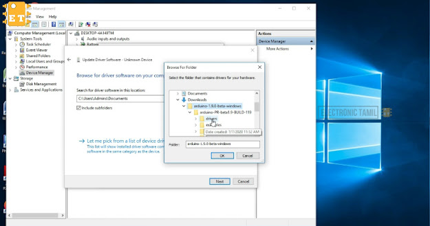
    How to enable com port for Arduino board -step by step


    right click on the "THIS PC" or "MY COMPUTER", then click Mange
    it open a new window,  In that select Device Manager and find the port of the board, 
    (connect the Arduino board and disconnect it, you can find the board)  

    Then double click the port 

    Then select the driver and click Update driver


    then click "Browse my computer for driver software" 


    then browser the Arduino driver folder


    after browse the folder then click next

    it start installing wait for a few minutes

    now click install and wait  
    now the drive will be installed. now close it 

    now it shows the port of the board .


    Youtube tutorial

    7 Jul 2020

    installation of arduino ide

    How to install Arduino IDE in window-10


    1.Open the Arduino official website (Arduino site)


    2.Then scroll down and Download the latest Arduino IDE or Arduino IDE (Beta)


    3.Then extract the zip file 


    4.Then create a shortcut file and send t to desktop 


    youtube tutorial


    Hey, we've just launched a new custom color Blogger template. You'll like it - https://www.electronictamil.ga/
    Join Our Newsletter